What is electronics design?
Electronics design is done before electronics production. We must first design our boards before we can produce them.
Electronic design can be done on softwares such as EAGLE which is an autodesk software. I will be using EAGLE for my electronic designs.
Workflow
- Schemetric Entry
- Board Layout
- (Auto)routing
- Simulation (can be done on CAMotics)
- Fabrication
Using Eagle
There are several parts that are needed in the Hello World Board. To be honest, it took me more time than I intended just understanding what part does what things. It was really confusing and EAGLE was a confusing software to use as well.
Main things I have learnt when designing my own board is that we must first have a microprocesser, the microprocesser is basically the "brain" of the board, storing the memory, programme as well as the pins. Other than that, there are the other peripherals which are different according to what you want the board to do.
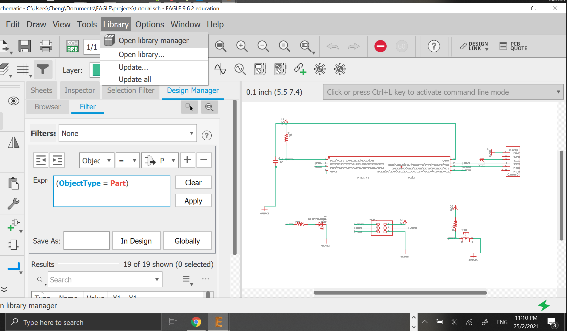
So, using EAGLE.
Before starting, we have to add the fab library to the EAGLE library. The fab library is a smaller library with components which are more commonly used in this course. Hence we will use the items from fab library instead of the larger EAGLE library.
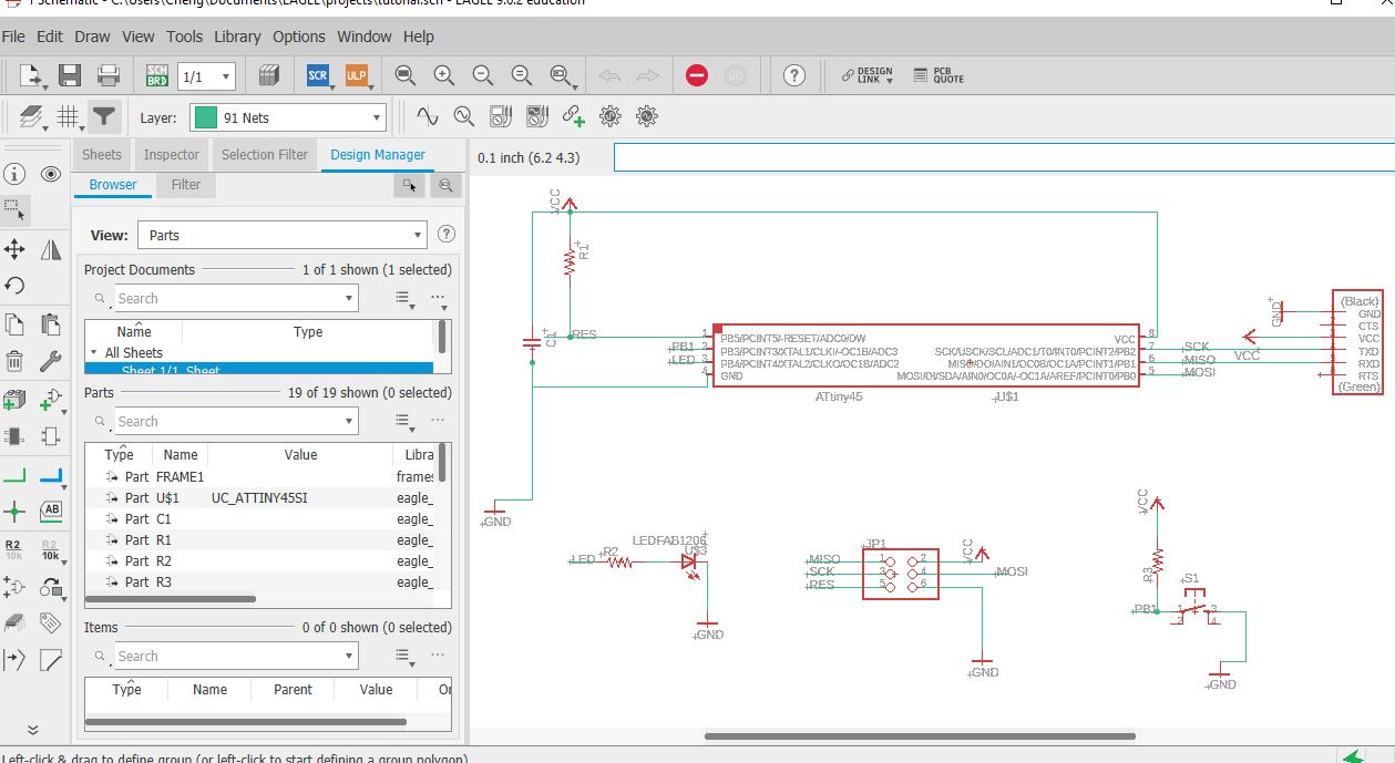
Hello Board
Schemetics of the Hello Board (done with EAGLE)
Once the schemetics were done, we need to switch to board and layout all of our components nicely. The main objective was to have no crosses and to have everything layed out neatly (route the board). This part was quiet fun, like a messy game of tetris. Probably the most interesting part in using EAGLES for me.
There is also a function for auto routing, it does not really give a good layout tho. What I did was to set the thing to auto route once and try to modify it to give a better design.
After alot of hard work, my hello board looks like this (the picture below)
Layout of the circuit board
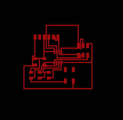
PNG of hello board traces
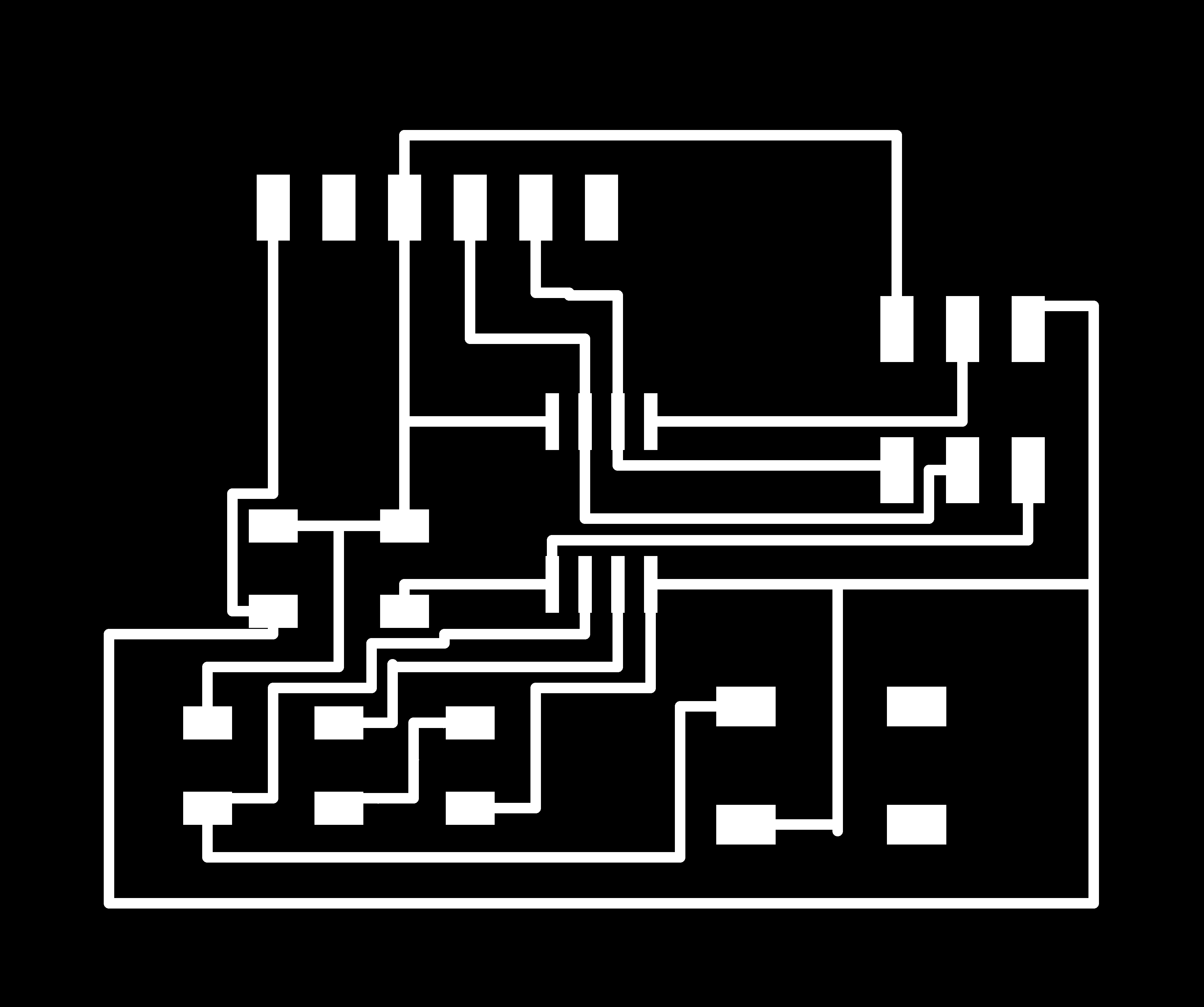
PNG of hello board boarder

Before milling the board, we have to put it through mods to generate the Gcode. I used the same settings as the ISP, hence the settings can be found in the electronice production page.
Similarly, before placing your Gcode into the stepcraft, we can run a simulation of it on CAMotics. It will allow us to see if the file is cutting what we intend to cut out. Once satisfied with it, we can then use the same Gcode on the CNC machine.
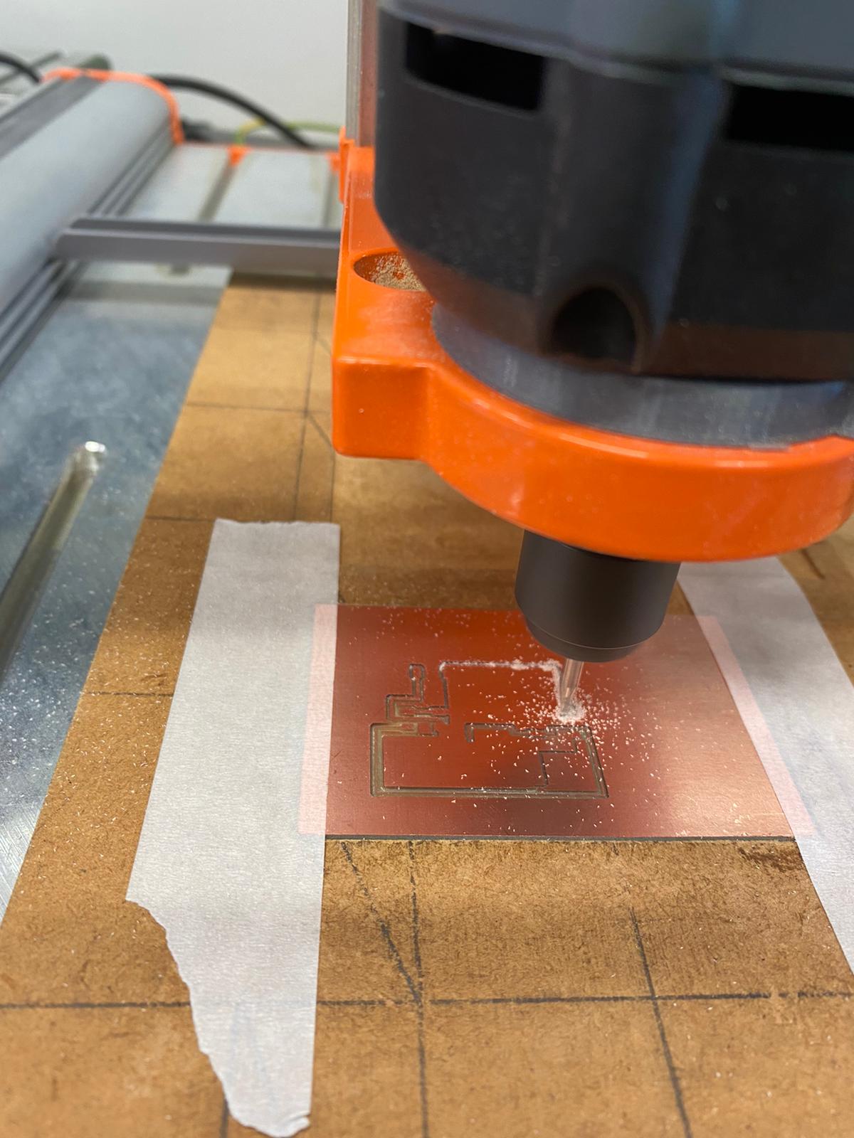
Milling of circuit board.
Do note that the end bit has to be changed when cutting the trace and the board. The bit cutting the mill is slightly bigger as it is cutting a larger area.
Hello-board after milling
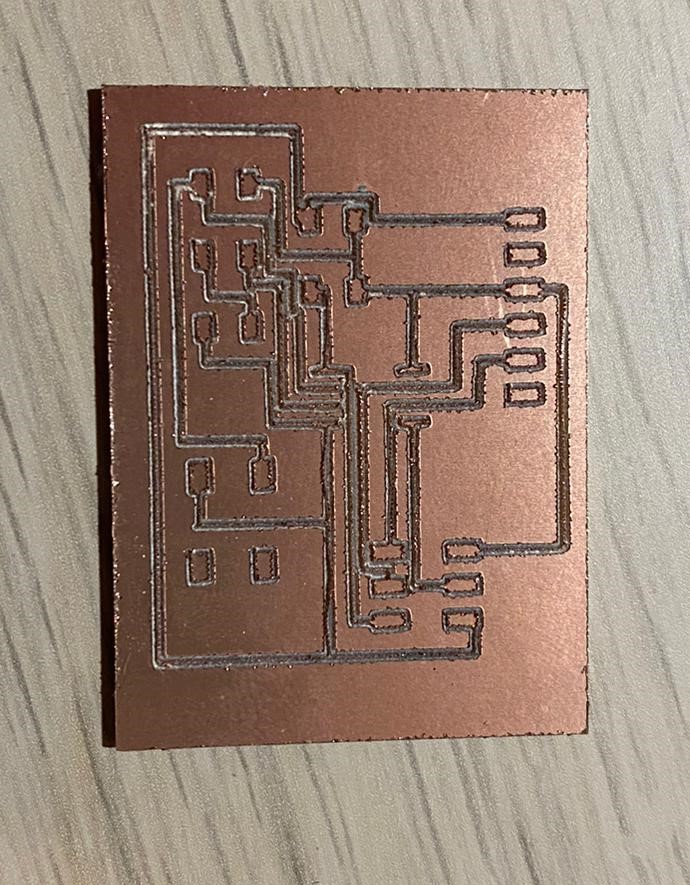
There were several errors after milling the hello world board. From the picture above, you can see that the traces were not clear. This could have occured from using the wrong drill bit, either of wrong size or one which was too blunt. This resulted in the traces to be really thin, hence some parts of the copper were not on the board anymore effectively making it a broken circuit. Hence, I was unable to stuff my PCB. I did not have enough time to make another one.